The manual pages themselves
Electrical system
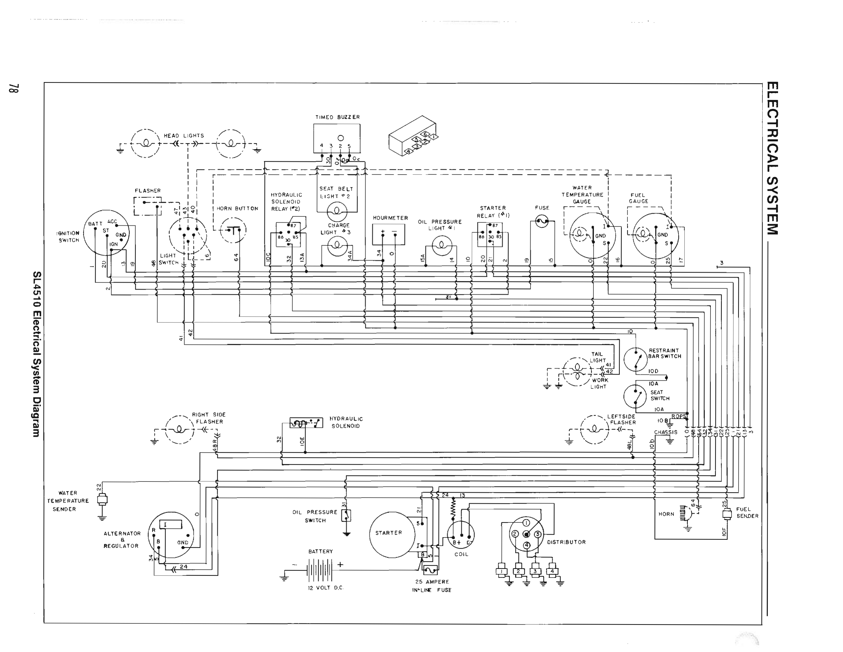
Traced from service manual 903931 p.78 (SL4510 Electrical System Diagram) with per-element provenance. 12 V DC · wet cell battery · 12 V starter · 37 A alternator (903931 p.3).
The interactive diagram below mirrors the manual page's component layout; the connecting lines
are logical links, not wire routes — the scanned diagram further down shows the
real runs. Flow animation shows conventional-current direction and is illustrative only.
Dashed blue elements are INFERRED (read from
adjacency, not printed labels) and carry their reason; everything else cites the exact scan region
it was traced from — click any component to see its citation crop. Verification gates:
overlay check + part-number audit, receipts in
receipts/sl4510-electrical-3d-2026-08-30/.
The optional narration (🔊 buttons and diagnosis-mode chimes) is a clone of Dane
Cooper's own voice — synthetic, consent-bound and watermarked, never a live recording.
Its words are generated from this page's text and each shipped clip passed a transcript check
against its script. This page has no offline cache, so the voice needs a connection.
| Fuse | Rating | Where | Protects | When it blows |
|---|---|---|---|---|
| Starter-circuit in-line | 25 A | at the starter B stud | everything — it is the master feed | entire electrical system dead (903931 p.76) |
| Instrument panel — part 071149 (holder 069745) | 20 A | instrument panel | gauges, panel switches, lights | gauges/lights dead, engine still runs |
Ratings CONFIRMED from 903931 p.76; part numbers from 904059 p.17. The alternator charge lead is unfused — remember that in the drain hunt.
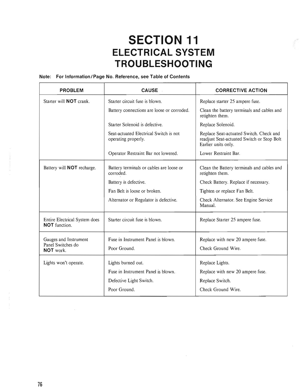
| Problem | Cause | Corrective action |
|---|---|---|
| Starter will NOT crank. | Starter circuit fuse is blown. | Replace starter 25 ampere fuse. |
| Battery connections are loose or corroded. | Clean the battery terminals and cables and retighten them. | |
| Starter Solenoid is defective. | Replace Solenoid. | |
| Seat-actuated Electrical Switch is not operating properly. | Replace Seat-actuated Switch. Check and readjust Seat-actuated Switch or Stop Bolt. Earlier units only. | |
| Operator Restraint Bar not lowered. | Lower Restraint Bar. | |
| Battery will NOT recharge. | Battery terminals or cables are loose or corroded. | Clean the Battery terminals and cables and retighten them. |
| Battery is defective. | Check Battery. Replace if necessary. | |
| Fan Belt is loose or broken. | Tighten or replace Fan Belt. | |
| Alternator or Regulator is defective. | Check Alternator. See Engine Service Manual. | |
| Entire Electrical System does NOT function. | Starter circuit fuse is blown. | Replace Starter 25 ampere fuse. |
| Gauges and Instrument Panel Switches do NOT work. | Fuse in Instrument Panel is blown. | Replace with new 20 ampere fuse. |
| Poor Ground. | Check Ground Wire. | |
| Lights won't operate. | Lights burned out. | Replace Lights. |
| Fuse in Instrument Panel is blown. | Replace with new 20 ampere fuse. | |
| Defective Light Switch. | Replace Switch. | |
| Poor Ground. | Check Ground Wire. |
The "Engine Service Manual" it refers to is the Ford 67/98 CID Industrial manual (KSG411/KSG416) — link in doc 09 §G.
Written for the Commercial Electric MS8301B. Three absolute rules: never in series with the starter or charging circuit (10 A fuse dies instantly — high-current paths get voltage-drop tests); never open/reconnect the circuit with a load on while the meter is in series; and move the red lead back to the VΩ jack before ANY voltage measurement — probing a battery with the lead still in a current jack is a dead short through the meter. It auto-sleeps after 30 min — press FUNC. Log every reading in the logbook.
Remove rings/watch; sparks near battery gas are the hazard, not shock. Keep the restraint bar up and stay off the seat — the interlocks hold the crank circuit open.
Free check 1: was the key left ON? Points ignition passes ~4 A key-on
(points usually stop closed) — that alone kills a battery overnight and burns the points.
Free check 2: clean/tighten both battery terminals and the cable ends (ground
063077, starter 075029); wash the dirt film off the battery top — it is a discharge path.
After charging: work lights on ~30 s (if fitted) or rest 2+ hours. A just-charged battery reads high and corrupts the baseline.
| Reading | State | Branch |
|---|---|---|
| ~12.6 V+ | full | go to Step 3 |
| ~12.4 V | ~75% | go on; note it |
| ≤12.0 V | discharged | charge fully first — draw tests on a flat battery mislead |
Record the number — Step 6's charging spec is relative to it.
Key OFF, seat empty, bar up, lights off. Lift the negative cable; red lead in the 10 A jack, DC A; meter bridges post ↔ cable clamp. A minus sign just means lead orientation — read the magnitude.
| Reading | Meaning | Branch |
|---|---|---|
| 0.00 on the 10 A jack | not yet proof — 0.01 A resolution hides tens of mA | confirm on the mA jack; only a mA-jack ~0 is a real zero → Step 6: the battery is dying of never-recharging, not theft |
| tens–hundreds mA | real drain | mA jack only below ~200 mA → Step 4 |
| ≥1 A | gross drain — the dead-overnight class | → Step 4; mind the meter's 2-min limit above 2 A |
| meter fuse blows at connect | drain is over 10 A — dead-short class | that IS the finding: skip series testing → Step 4 fuse pulls + Step 5 disconnect; inspect cables for chafe-through |
The 25–50 mA "normal" allowance belongs to computerized vehicles — applying it here masks the fault. Overnight self-discharge is ~0.2–0.5% — never the explanation.
Battery negative still off. Lift the meter off the negative post before wrenching — while it bridges, a wrench-to-chassis touch at the B stud blows its 10 A fuse silently, and a dead meter reads 0 A (which the table below would misread as "draw gone"). Remove the nut on the alternator B terminal, lift and tape the lug. Re-rig the Step-3 series meter, confirm it still shows the Step-3/4 drain (or beeps on continuity), then read.
| Result | Meaning | Action |
|---|---|---|
| draw gone | shorted rectifier diode or field/regulator stuck energized (~3 A class; intact diodes leak only µA). Factory-class line (CLAIMED, Prestolite family): >60 mA through the disconnected B lead = alternator leak — and this model has no isolation diode, so the rectifier sits directly across the battery | alternator 075863 = Prestolite 8AR2169F (aftermarket Leece-Neville 110-629) / regulator 075864 = OE 9RC2066 — a 4-screw plug-in module, a driveway job; belt 069152 while in there. Never pull the output lead with the engine running |
| draw unchanged | alternator innocent | inspect cables 075029/054985 for chafe-through; re-test the ignition switch by dropping its BATT feed |
Reconnect everything (25 A fuse back in) and move the red lead back to the VΩ jack first — Rule 3. The baseline must be a FULL battery's rest voltage (~12.6 V) — judged against a half-charged 12.4 V rest, a healthy 14.4 V system false-alarms as "overvoltage"; recharge and re-baseline if Step 2 read below ~12.5 V. Seat occupied + bar down = the machine is live: controls neutral, area clear, away from fan/belt. Engine running, DCV at the posts. Ford's factory spec is relative (CONFIRMED — factory pages 4-02/4-03; the full-charge baseline above is the factory's own precondition): at ~1500 rpm no-load the reading must be +1.0 to +2.0 V above your Step-2 resting voltage; at ~2000 rpm all loads on, at least +0.5 V above; more than +2.0 V above = regulator overvoltage. No rise → belt 069152 (adjust per 903931 p.91), excitation (this unit is ignition-excited — check the charge-light circuit 072345), a bad cable/connection, or the alternator/regulator. Before buying an alternator, run Step 7 on the charge path: fast idle with loads on, alternator B stud → battery + and battery − → block; over ~0.5 V total = cable/connection fault, not alternator (the factory table's own first cause). Keep clear of the fan and belt whenever the engine runs — probes go on with everything stopped. Ripple hint: AC V 4 V range across the battery — near ~0.5 VAC suggests a bad diode, but this meter is average-responding/40–400 Hz, so it corroborates Step 5, never replaces it. Charge light: ON with key/engine off is correct, OFF when running; stays on = not charging; never lights = bulb/feed — and a dead charge-light circuit can mean a never-exciting alternator. Do not full-field this alternator: the Ford book's A-to-F jumper test belongs to Ford's external-regulator layout; 075863 carries its regulator on the unit, and full-fielding an integral-regulator alternator risks unregulated output (factory p.4-04, architecture fence).
Disable the ignition first so the engine spins but cannot fire — lift the coil-to-distributor high-tension lead and clip it to the block (or disconnect wire 13 at the ballast resistor). With live ignition a healthy engine just STARTS, with your hands beside a spinning fan. Attach probes with everything stopped; crank in ~15 s bursts with rest between; reconnect the lead afterwards.
| Probe points (while a helper cranks) | Fault threshold |
|---|---|
| battery − post → engine block | >~0.2 V: clean/retighten ground cable 063077 |
| battery + post → starter B stud | >~0.2 V: clean/replace starter cable 075029 |
| starter B stud → starter case | reads the voltage at the starter (not a drop): should stay above ~9.5 V cranking; lower = sum the two drop rows + battery (R&R 903931 p.86) |
Night 1: full charge, log Step-2 voltage, negative cable OFF overnight. Night 2: cable ON, everything off. Cable-off up + cable-on dead → machine drain confirmed (Steps 3–5 find it). Cable-off ALSO down → the battery or its dirty case top, "new" or not. Both fine → intermittent, or short-run usage never recharging (Step 6 numbers decide).